- Part number : 119-903217-01
Small 1.5V SMD Electro Magnetic Buzzer Sound , 5.5 OHM Magnetic Buzzer
Quick Detail:
- Size: D9.0mm*H3.2mm
- SPL: Min.83dB at 10cm Input 2700Hz/1.5Vo-p 1/2 Duty Square Wave
- Coil Resistance: 5.5+/-1 ohm
- Operating Voltage: 1-3Vo-p
- Rated Current: Max.100mA Input 2700Hz/1.5Vo-p 1/2 Duty Square Wave
Description:
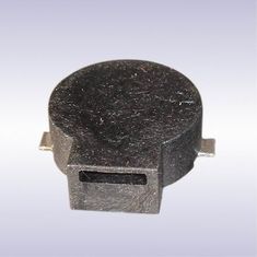
- buzzer
- SMD Electro-Magnetic Buzzer
- SMD Electro-Magnetic Element
- 1.5V Buzzer
- thin and small Buzzer
Specification:
1. Technical Parameter
Measuring condition
Part shall be measured under a condition (Temperature: 5~35℃, Humidity: 45%~85%R.H., Atmospheric pressure: 860 ~1060hPa) unless the standard condition (Temperature: 25±3℃, Humidity: 60±10%R.H. Atmospheric pressure: 860 ~1060hPa) is regulated to measure.
1 | Rated Voltage | 1.5 Vo-p |
2 | Operating Voltage | 1.0~3.0 Vo-p |
3 | Rated Current | Max.100mA ,at 2700Hz 50% duty Square Wave 1.5Vo-p |
4 | Sound Output at 10cm | Min. 83dB,at 2700Hz 50% duty Square Wave 1.5Vo-p |
5 | Coil Resistance | 5.5±1Ω |
6 | Resonant Frequency | 2700Hz |
7 | Operating Temperature | -20℃~+70℃ |
8 | Store Temperature | -40℃~+85℃ |
9 | Net Weight | Approx 1g |
10 | RoHS | Yes |
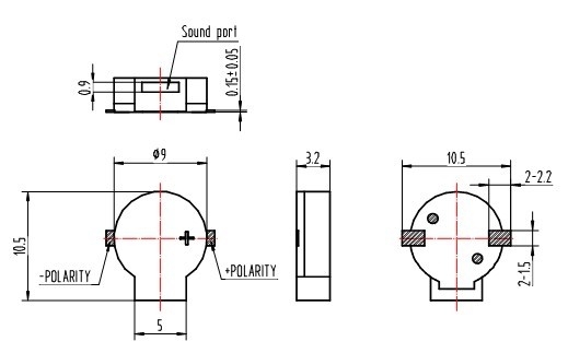
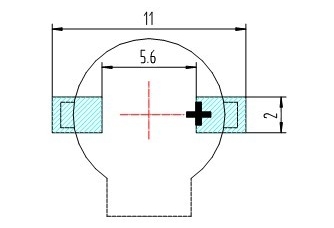
*Unit: mm; Tolerance: ±0.3mm Except Specified
*Housing Material: Black LCP
*Terminal plate: 2 soldering pads, tin Plating Brass
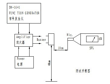
3.Electrical And Acoustical Measuring Condition
Recommended Driving Circuit
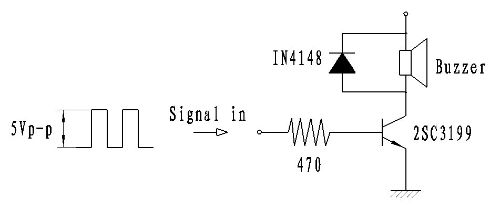
Resonant frequency, 1/2 duty cycle. Square wave.
Signal amplitude should be large enough tosaturate
the transistor.
Recommended Setting
4.Frequency Response
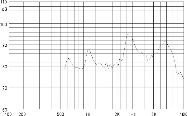
1.5Vo-p 50% duty Square wave,10cm
Surface mounting condition
(1)Reflow soldering
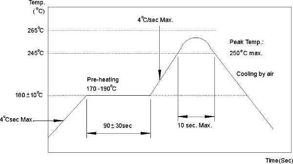
Note:
- In automated mounting of the SMD sound transducers on PCB, any bending, expanding and pulling forces or shocks against the SMD sound transducers shall be kept minimum to prevent them from electrical failures and mechanical damages of the devices.
- In the reflow soldering, too high soldering temperatures and too large temperature Gradient such as rapid heating or cooling may cause electrical failures and mechanical damages of the devices.
(2) Soldering pattern
Reliability Test
After any following tests the part shall meet specifications without any degradation in
appearance and performance except SPL. SPL shall not deviate more than -10 dB
from the initial value
(1)Ordinary Temperature Life Test
The part shall be subjected to 96 hours at 25±10℃. Input rated voltage
Test Resonant frequency, 1/2 duty Square wave.
(2)High Temperature
The part shall be capable of with standing a storage temperature of +85℃ for 96 hours.
(3)Low Temperature Test
The part shall be capable of with standing a storage temperature of -40℃ for 96 hours.
(4)Humidity Test
Temperature:+40℃±3℃ Relative Humidity:90%~95% Duration: 48 hours
and expose to room temperature for 6 hours
(5)Temperature Shock Test
Temperature:60℃ /1hour→ 25℃/3hours→-20℃/1hour→ 25℃/3hours (1cycle)
Total cycle: 10 cycles
(6)Drop Test
Standard Packaging From 75cm(Drop on hard wood or board of 5cm thick,
three sides, six plain.)
(7)Vibration Test
Vibration:1000cycles /min. Amplitude:1.5mm, Duration: 1 hour in each 3 axes
(8)Reflow Test
Use recommendable reflow soldering condition (as shown in 5.1)
No abnormality should be found after reflow
Good soldering to meet soldering requirements
Note:
As this product is not protected from foreign material entering, please make sure that any foreign materials (e.g. magnetic powder, washing solvent, flux, corrosive gas) do not enter this product in your production processes. The functional degradation (e.g. SPL down) may occur if foreign material enter it
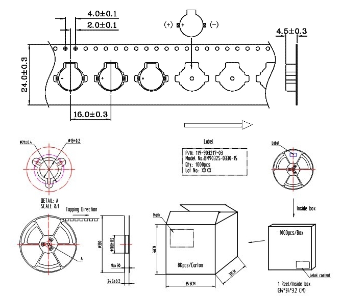
Packing